Arkanoid Cocktail Cabinet

Arkanoid-Logo-New

About 13 years ago (2001), my brother, dad and I embarked on a mission to create some arcade cocktail cabinets. My brother had bought some vintage arcade games at auction, and we both decided that it would be fun to own brand-new cocktail tables.

We got my dad on-board with the idea, which was probably the most important part, since he had all the tools and know-how. And if we were going to build 2, we might as well build more. We ended up creating 6 cocktail cabinets; one for each sibling in our family, one for a cousin, and another for a neighbor. This original endeavor is somewhat documented on my very old personal site.

The Cabinet

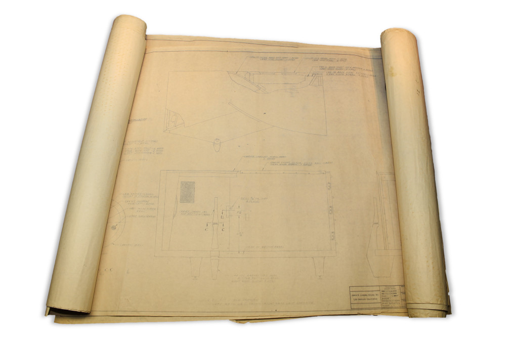
The first thing we did is measure an actual cocktail cabinet that we found at a local Marie Calendar’s. The cabinet was actually pretty terrible. It didn’t appear to be authentic, and was in bad condition. That aside, it gave us some basic ideas for size and construction.

IM000185

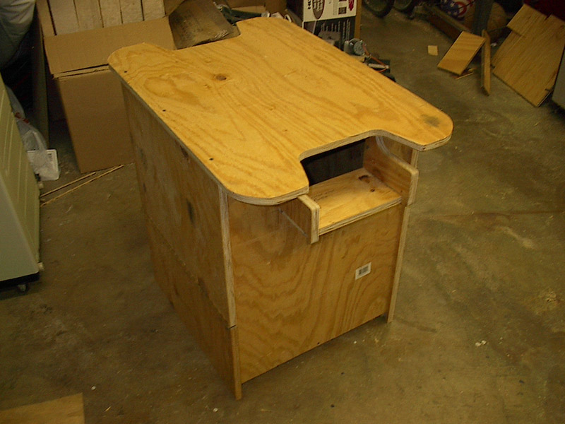
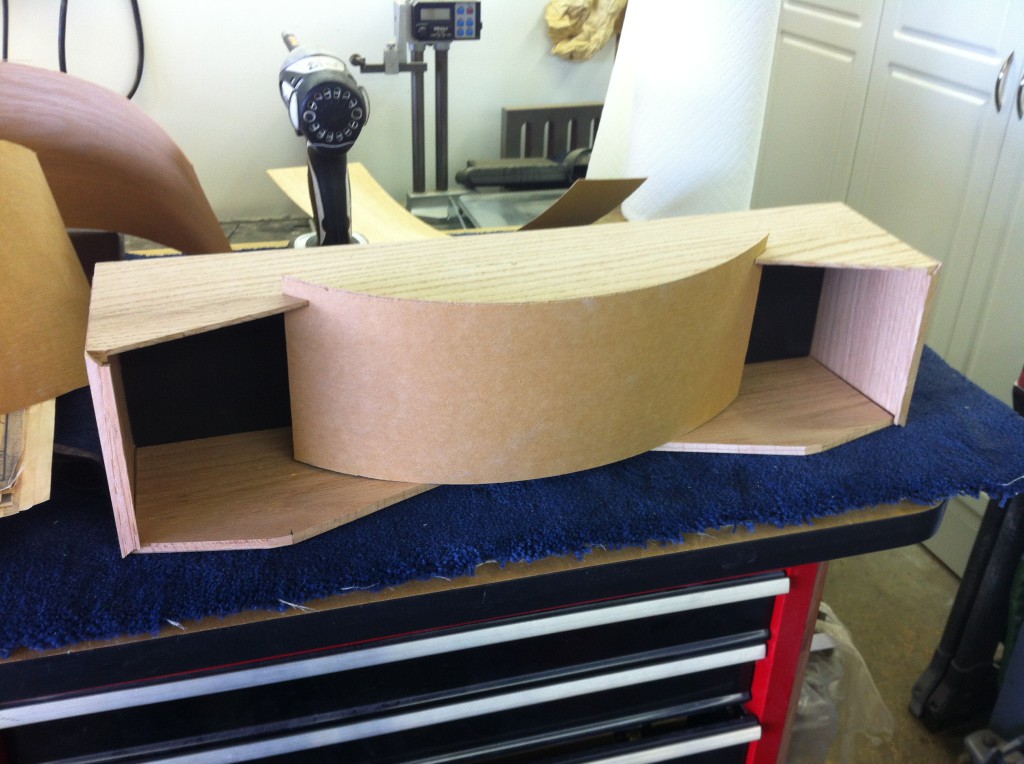
We build a rough prototype out of some old plywood that we had lying around in the garage. It was very crude, but it helped us cement down some measurements and figure out how we would do this with the actual cabinets. It was quickly built with ugly butt joints and no thought to finish in one evening. We then wrote down some final measurements and made plans for how to construct the final cabinets.

IM000209

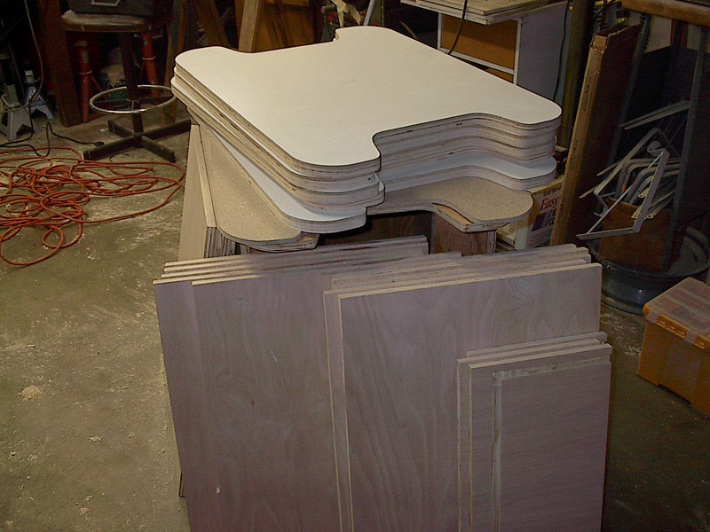
For the final cabinets, we used plywood with oak veneer. We used 3/4 throughout with the exception of the top which was 3/4 and 1/4 laminated together to make a substantial 1 inch thick surface. The pieces were all cut out on the table saw. We decided to use dados throughout the construction in order to eliminate the need to nails and screws. We wanted the finished product to look elegant and not cheap.

IM000270

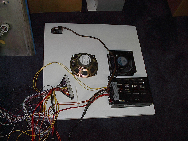
The bottom piece is made of particle board with a melamine layer on both sides. holes were pre-cut for a speaker, AC receptical, and fan. The power supply was also mounted to the bottom piece.

IM000314

All of the sides were fitted together and glued. The dados provided strong joints once glued. For the door, we attached it using european hinges instead of unsightly piano hinges that are common on arcade cabinets. Since this is for personal use, we made no effort to make the cabinet lock. The edges were all routed with a groove in order to accept t-molding, however some of the cabinets were fitted with edge-tape veneer instead.

IM000215

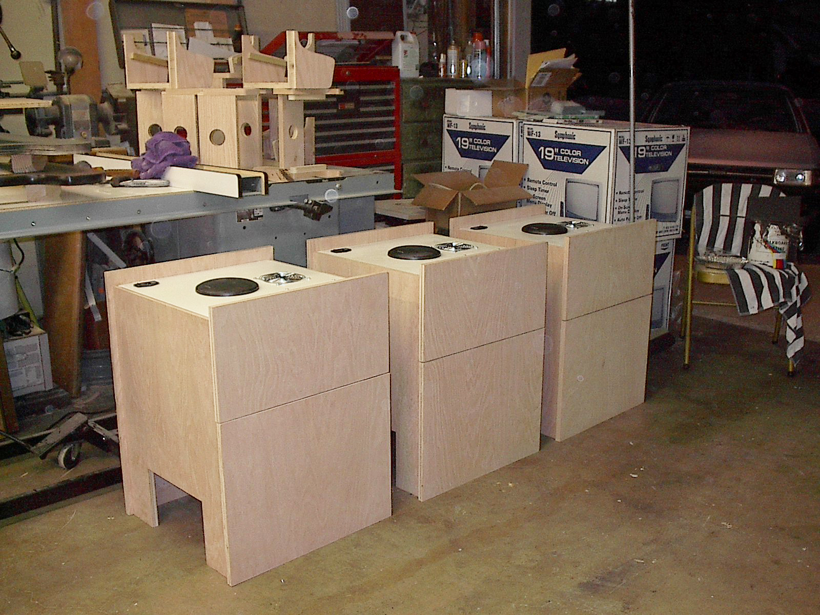
The tube is actually a cheap 19 inch CRT TV that we bought from Fry’s and then converted to accept the arcade video signals. For some reason, they sales person didn’t believe us when we asked for 6 19 inch CRT TVs…

IM000516

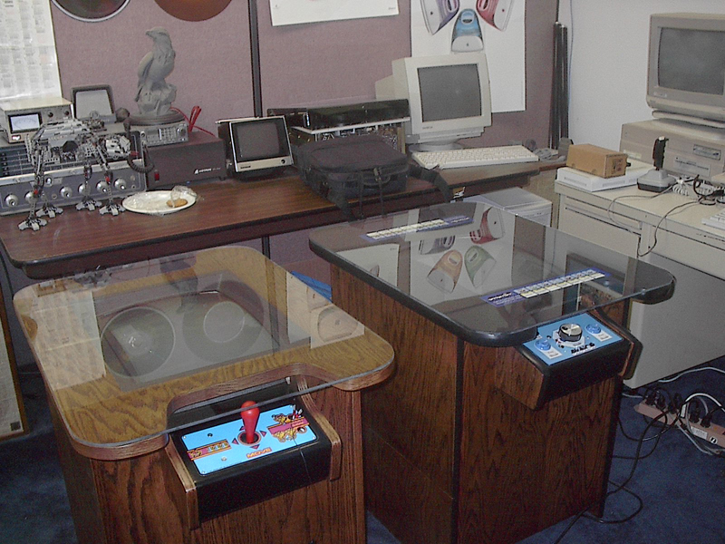
Of all of the cabinets, only 2 got 100% completed; mine, an Arkanoid, and my sister’s, a Mrs. Pac-Man. My other sister, who was in college at the time, didn’t want her’s put together since she had no place to put it, so it sat in storage in pieces.

Ten Years Later

My sister was hosting a family reunion, and wanted her cocktail cabinet for the kids to play on. I had agreed to finish her cabinet for her when she had a permanent dwelling. The time had come, but I didn’t have enough lead time to prepare it for the reunion. En lieu of her cabinet, I gave her my Arkanoid, leaving me with the unassembled cabinet in storage.

Over the last month or two I’ve been collecting all the pieces I needed in order to complete this game, including power supply, controllers, PCB, buttons, and the control panel overlay.

IM000213

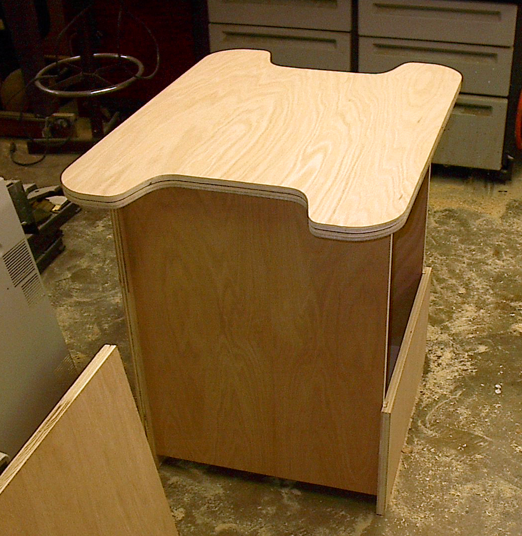
I assembled the cabinet by simply gluing the awaiting pieces together. It went together perfectly. Even the hardware for hinges was already in place in storage, so there was little to do there. This cabinet had its edged veneered instead of using t-molding. This is was actually preferable to me as I found that I didn’t like the look of the t-molding on my original cabinet after a while. I stained it using a red-wood colored Minwax. This time I opted for a red stain over the brown that I used for my original. From there I spent a weekend putting a clear coat of Deft over it.

IMG_1606_edited

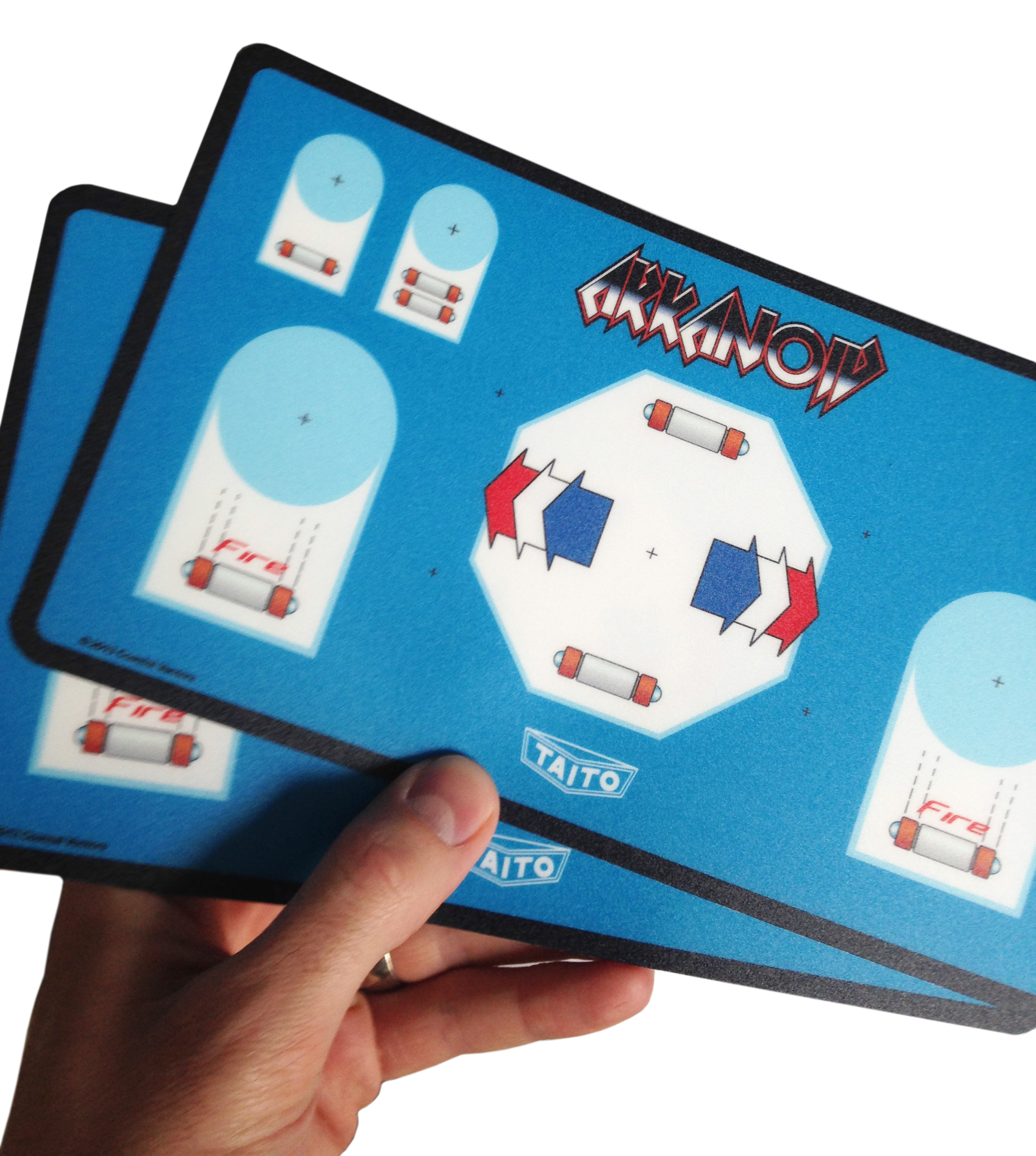
I took the original design file for the control panel overlay that I made back 10 years ago, and updated it significantly. I cleaned up some mistakes, and updated some of the graphics to look cleaner than before. (Before, I barely knew how to use Illustrator). The first time around, I printed them on photo-paper and put them under a thin sheet of plexi-glass. This time, I had them printed at ArcadeOverlays.com, and they turned out great!

IM000303_edited

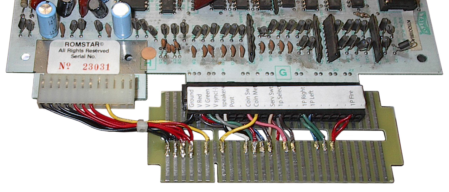
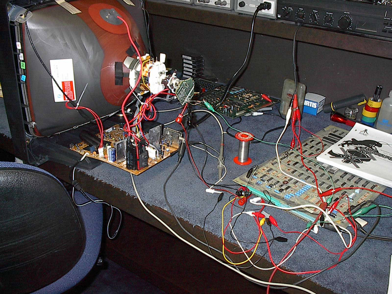
We fitted all of the cabinets with Jamma. This made it easy to swap games in and out if we ever needed to. The Arkanoid 1 PCB needed a custom Jamma adapter whereas Arkanoid 2 comes with a Jamma connector as standard. I build a converter board for my Arkanoid 1 PCB so I could quickly switch between Arkanoid 1 and 2.

IMG_1607

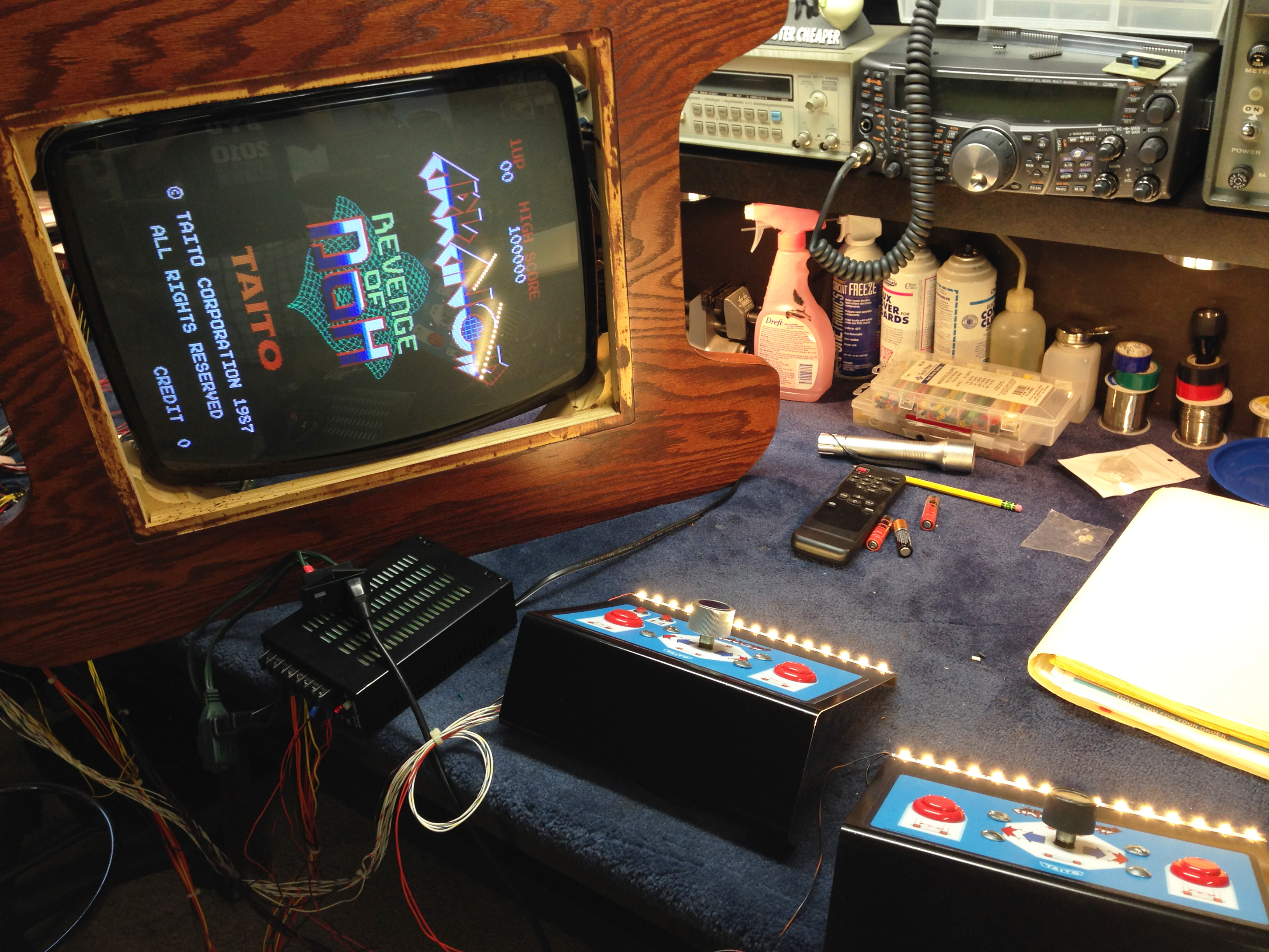
I spent about an hour putting all the connectors on the wiring harness, and hooking up all the controls, power, and monitor. I hooked it all up on the bench, and verified that everything worked, and it did! Another change I made was using an LED strip for the panel illumination instead of bulky, hot incandescent lights.

IMG_1658

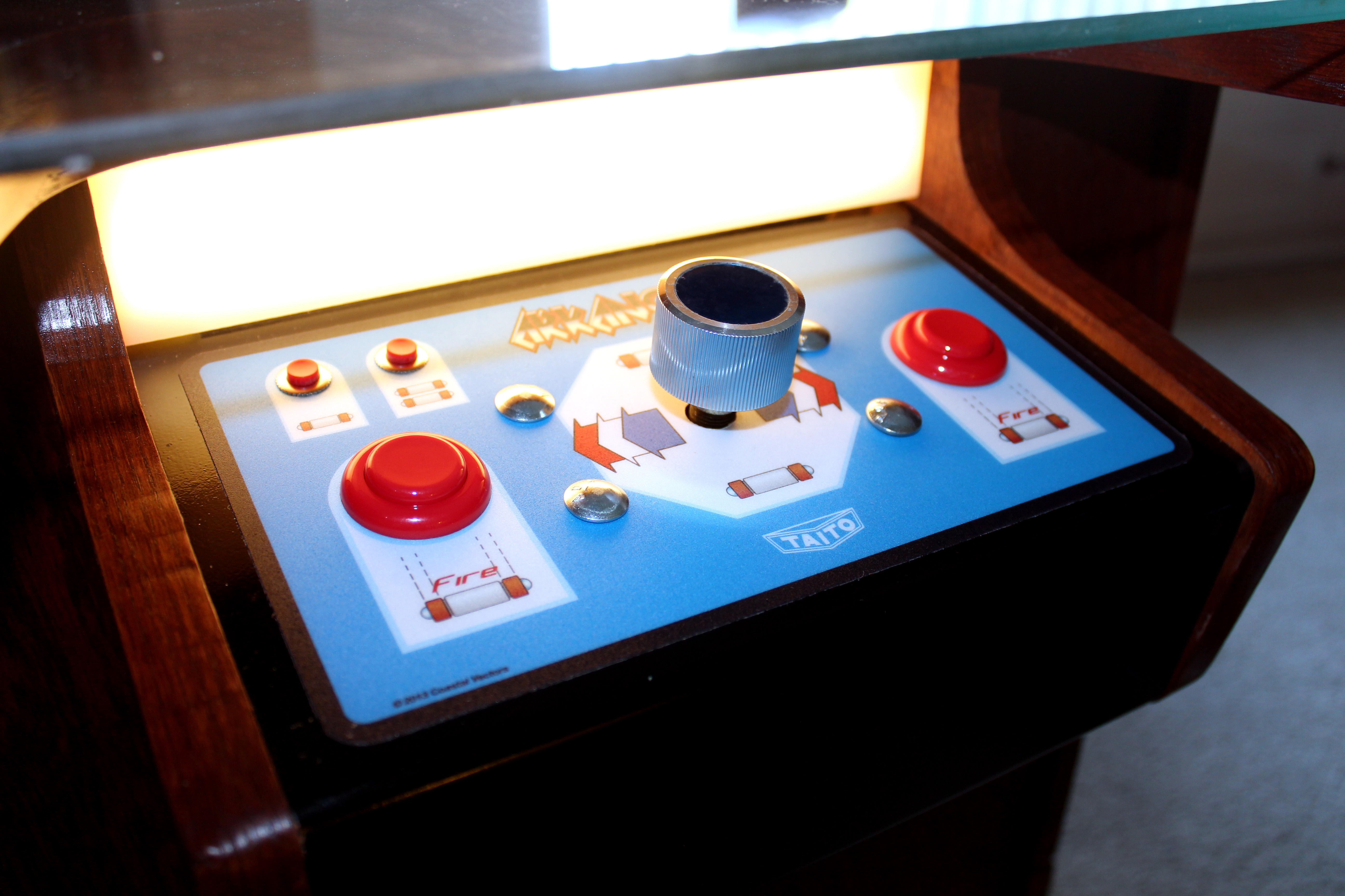
The control panels are made from sheet steel. I had a friend who works in a metal shop who bent them on his brake for me. I then drilled all the holes using a template I made in Illustrator based off of the design I had printed, and drilled the holes on a drill press. It was panted with black lacquer, and then I carefully placed the CPO sticker on. That was the most nerve wracking part!

IMG_1688 edited

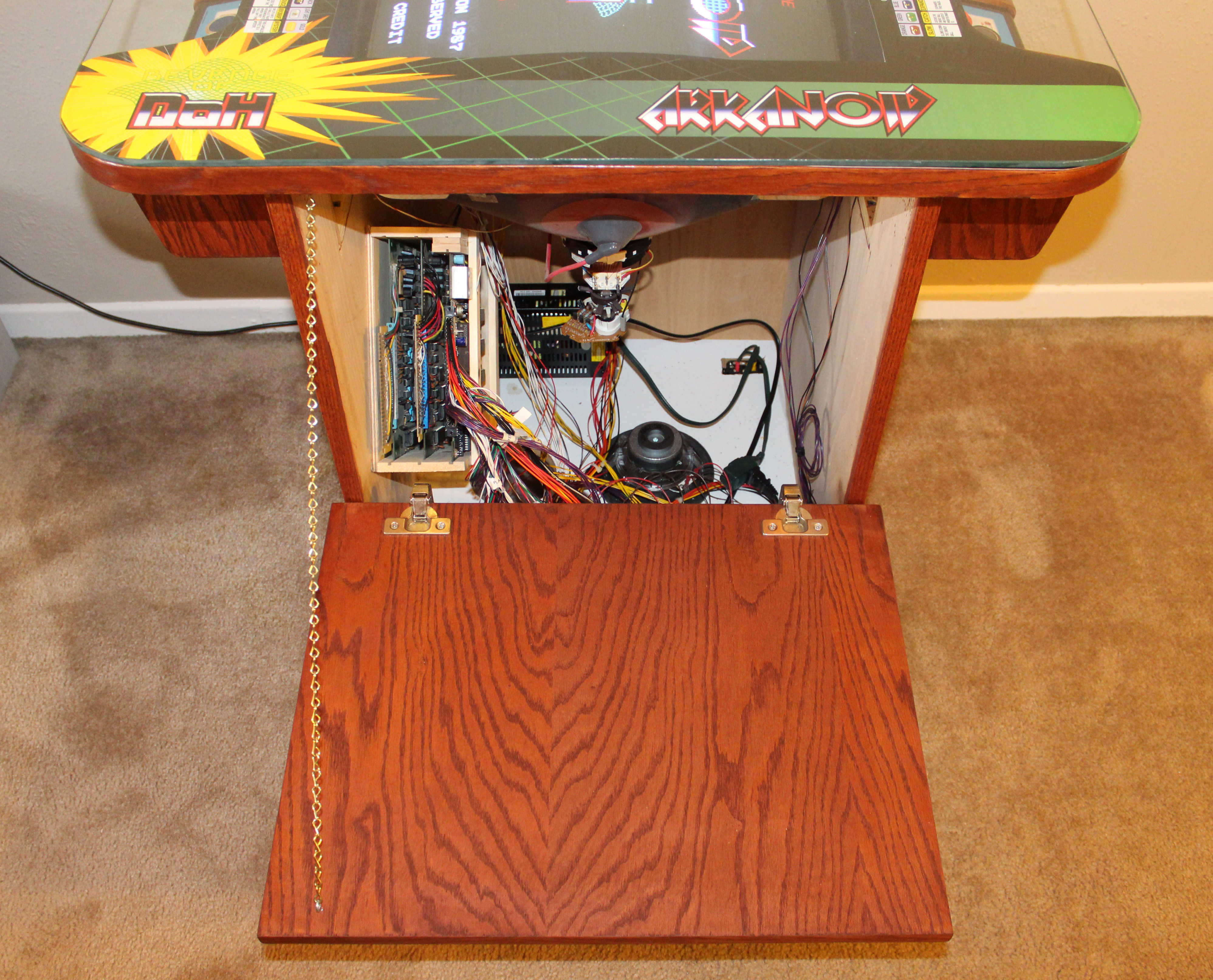
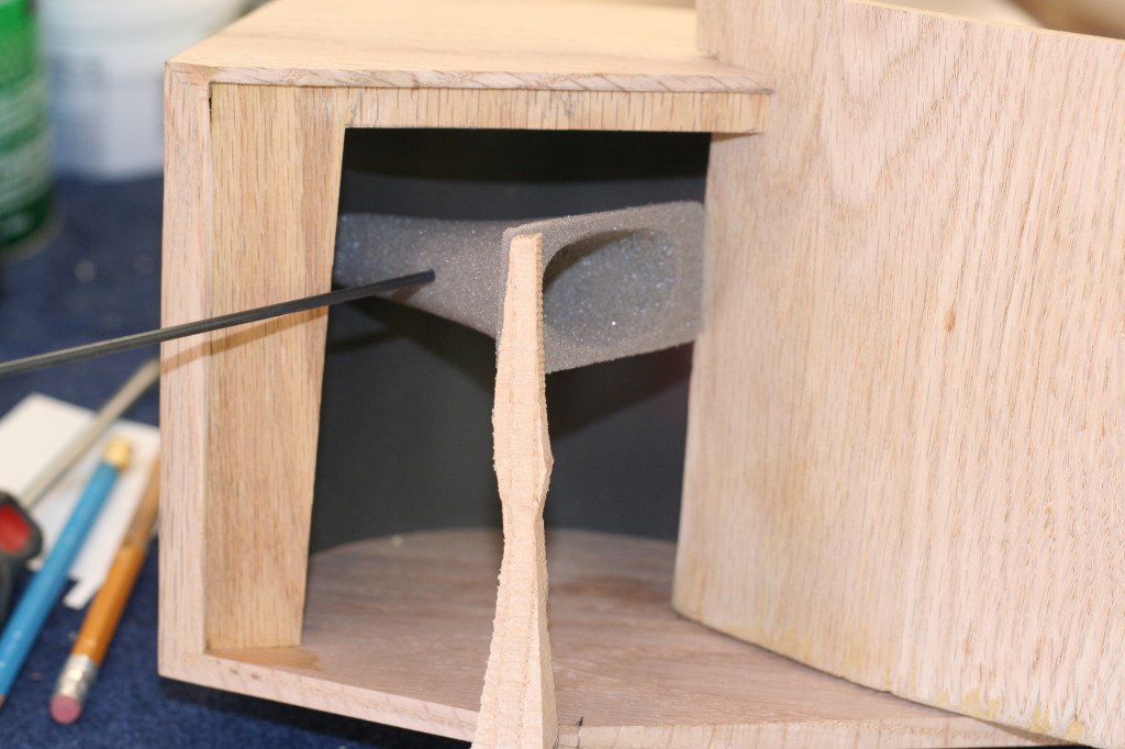
Once I had all the electronics working, and ready to go, all that was left was to stick it into the box. I made a little box that you can see on the left for holding the PCBs. It fits 3; Arkanoid 1, Arkanoid 2 and Tournament Arkanoid. Everything fit like a glove!

IMG_1685_edited

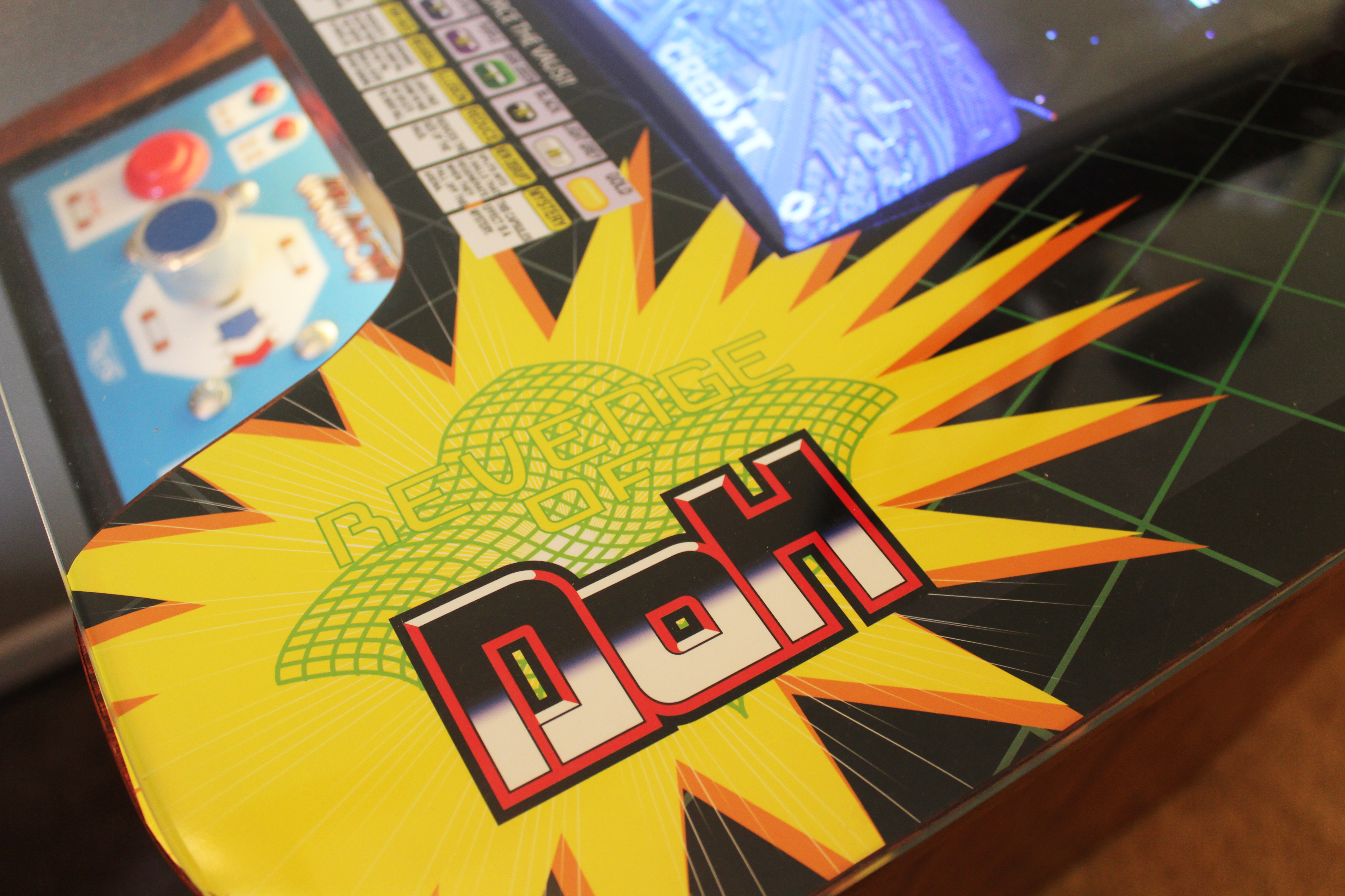
I made some top artwork a while ago in anticipation of this project. The design was meant to be retro, and a little cheeky. I’m not sure that will be a permanently displayed… It was printed on a friend’s large format printer, and then I cut it out with an exacto knife. I have a new design that’s a little less in-your-face that I’m contemplating printing…

The Finished Product

IMG_1683_small

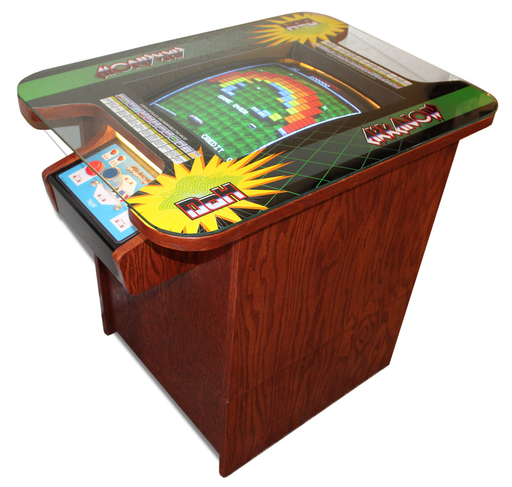
All-in-all, the cabinet turned out great. I’m very pleased with the look of the cabinet, as well as with the game itself. I quite enjoy Arkanoid, and enjoy having Arkanoid 2. It’s a little different but still familiar. I don’t think I’ll get tired of it soon.

Miniature JBL Paragon Project

Paragon

In 1957, James B Lansing introduced a gorgeous and iconic loud speaker system called the D44000 Paragon. The JBL Paragon was a high-end stereo speaker enclosure. It contained 6 drivers in it’s spacious 9 foot enclosure; two mid-range horns, two tweeter horns, and two woofers. The enclosure was made of beautiful, contoured, stained hardwood. It is, in my opinion, as much a work of art as it is functional musical equipment. The curves, reminiscent of the 50’s contemporary design doesn’t look out of place in any modern setting.

Paragon-Diagram

The entire enclosure was designed to efficiently deliver balanced and powerful audio to a (very) large room. The two woofers set inside the cabinet act as drivers for a left and right channel horns that are made of the enclosure itself. This system is capable of immense power.

Dad and Paragon Small

My dad built one of these back in the 60’s when they retailed for $2,500.00. We all grew up in our house listening to this magnificent speaker, and have grown to love both the aesthetics and sound that it produces. With only a little more than 1000 ever produced, Paragons can fetch more than $25,000 at auction, and are very sought after by collectors.

I have always wanted to have my own Paragon, however they are generally cost prohibitive. Even building from scratch can cost multiple thousands of dollars. Beyond that, the large footprint is another limiting factor. Perhaps someday this will be achievable, but for now, I am going to have to settle for something a little more achievable; a 1/5th scale Paragon.

IMG_0143

This replica is a fully functional 4-way shelf speaker system. It has functioning horns, and replicates every nuance of the original Paragon en-miniature.

I’m exited to share some of the details of creating this miniature Paragon with the hope of bringing others to appreciate this piece of HiFi history, or perhaps just to inspire others to embark on similar creative projects.

Scaling Down

plans

The first step was scaling down all the measurements. My dad still has the original plans for the Paragon that he purchased from JBL back in the 60’s. We toyed with various sizes, and decided that 20 inches wide would be a comfortable size for bookshelf speakers without becoming too unwieldy. That worked out to be about 1:5, so that’s the scale we stuck with.

I went through the plans and scaled down all the major measurements by 5, and drew up basic plans in Adobe Illustrator. Obviously at this scale some liberties could be taken with the box interior. The exterior however is the part that we most wanted to emulate, and so we took great care to be as faithful to the original as we could while scaling down.

Horns

It was agreed that the horns, providing the iconic look of the Paragon, would be one of the most crucial elements of this project. We started from here to make sure we could get a viable result before investing time in the other aspects of the cabinetry.

The horns went through multiple redesigns and trials before finally getting a usable result. The very first horn we tried was hand sculpted from foam and then covered in a latex based paint with the intention of creating a mold from which we could cast more horns.

IMG_8404

The result was just not accurate enough, and I then took it to the next step. I modeled the horn as accurately as possible using Autocad Inventor, and then had a horn 3D printed using Shapeway’s service. The result was remarkable.

CadHorn

We took this sample and then created a mold and cast half a dozen additional horns. Unfortunately, the resulting horns with susceptible to sag over time and had to be scrapped. The 3D printed horns, though more expensive, proved to be more resilient.

IMG_8652

We had to do another redesign to make the horn fit a little better. We made test prints using a MakerBot and then ordered the final pair from Shapeways once we were convinced it was perfect.

horns

To get the gold front on the horn, we tried painting with multiple metallic paints, however each proved to not give an even luster. Finally, we bought paper-thin brass that we cut to the exact size, brushed, and coated with a protective enamel to prevent tarnishing. This was then epoxied to the front of each horn. The result looks fantastic!

IMG_0100

Legs

The legs were another trial-and-error endeavor. We cut some raw wood on a band saw to the approximate shape of the leg, then tried to shape the leg by hand, as one would do for the full sized Paragon leg. This proved to be difficult with such a small model, and we decided that a higher-tech approach should be used.

This necessitated the purchase of a small CNC machine that proved to come in handy throughout the project. Again using Autocad Inventor, I modeled an accurate representation of the leg, scaled it down to 1/5th scale, then exported the file as an STL file which we then used to make a CNC program to cut the legs out programatically.

IMG_1068

The result was once again fantastic. and made the project even that much more exciting to be working on.

leg

Prototyping

We started by experimenting with Oak. We cut our all the basic parts for out of 1/4 inch thick red oak using a table saw and band saw. The basic shape was formed with the top, bottom and two sides. These for were all joined with 45 degree mitre joints.

IMG_0406

The front reflector is made from layers of laminated veneer. We made a jig with the correct curvature and then formed the reflector using contact cement and 5 layers of plywood. This made it the correct scale thickness.

Everything was trimmed and fitted. We placed some structural pieces inside to hold the drivers that were purchased for the project. 1/5 of the original 15 inch drivers worked out to be 3 inches which is what we purchased. The drivers don’t scale linearly in all three dimensions unfortunately, and they were too deep (long). This meant having them face the wrong direction inside the cabinet.

The inside curvature was accomplished by bending some thin steel, and painting it flat black. The steel held the shape very nicely, but it gave the box a tinny, bright quality when we first tried it. This was corrected by adding a sticky sound dampening material onto the backside. It made an immediate improvement.

IMG_8634

The prototype was finished off with the mounting of the horns.

IMG_1355_edited

Final Cabinet

Once we had the measurements down, it was time to move on to using the correct wood. We bought planks and planks of quarter-sawn walnut to make the final paragon out of. All the wood planks were cut on the band saw to a .3 inch thickness.

IMG_1053

The wood was then planed and sanded down to a .25 inch thickness.

IMG_1062

We then we used a CNC machine to cut the majority of the raw parts.

IMG_1056

With the rough shapes done, we just needed to sand and prep for assembly. With so many intricacies, finding the right order for assembly was difficult!

All the wood was cut, sanded, and then filled to make the surface as smooth as possible. Additional sanding and the application of Danish Oil to color the wood completed the enclosure.

During this process we made some design changes to make it even more accurate. You could call it feature creep, and it felt like the project would never get done! The perfectionism was worth it, however, after seeing the box come together and get stained. It looks beautiful!

IMG_0102

Electronics

I bought an off-the-shelf amplifier to be used with the speakers that we chose. However scaling down the audio to such a small unit left some weird acoustical anomalies that the amplifier did not account for. There were some obvious frequencies that were masked and others that were accentuated by the size of the miniature box. We couldn’t find an amplifier with built in adjustable equalizer that would allow us to tune the frequency response curve.

IMG_1933

Ultimately, my dad designed his own using a special amplifier with 5 parametric equalizers in a single chip. The circuit board was layed out in Eagle, purchased, then we soldered on all the components and had ourselves a working amplifier small enough to fit inside the paragon. My brother programmed a PIC processor that controls the volume and equalization values.

The volume *** controls the overall volume, and when pressed in, controls the level of the subwoofer.

Speakers

The miniature Paragon is a 4 way speaker system. There is an internal housing for two 3-inch full-range speakers. These provide the main left and right audio channels.

m5n-psm

We found small tweeters that are 1/2 inch in diameter to use to power the horns. These are driven off of the main left and right channels via a passive crossover. The tweeters add to the higher end of the frequency response where the full range speakers begin to be less efficient. Additionally, it makes the Miniature Paragon more authentic and interesting.

Subwoofer

When we first listened to it, we noticed that it lacked bass. To fix this we added a 5 inch down-firing subwoofer in order to fill out the sound a little better. We created a plain 7 inch cube to house the 5″ sub, and added the same metal feet that are being used on the rear of the Paragon.

We felt it made more sense to contain the electronics in the Subwoofer, and let the paragon be tethered with only a single wire rather than with 3 (Power, Aux in, and Sub). This elicited a need for a control panel that would not look out of place.

We opted for an engraved brass plate to contain the wire connectors. The engraving was able to be accomplished using the same CNC machine that used for the woodworking. We used a diamond tip bit and drew up some artwork using Adobe Illustrator.

It took a few tries to get the speed right for the brass to be clean, but we finally did get it just right, and they turned out beautiful.

IMG_0070

After engraving, they needed to be filled with a black filler to accentuate the lettering. Finally, they needed to be coated with the same protective clear-coat used on the horns to prevent tarnishing.


Putting it all together

Finally the whole unit is completed!

IMG_0098

The resulting quality is amazing, and in some cases it’s hard to even tell that it is miniature when there are no object for comparing scale.

IMG_0115

This has truly been a challenging, but completely worth-while project!

IMG_0085

Starfleet Badges

As most self-respecting nerds are aware, Star Trek: The Next Generation is being re-released in high-definition Blu-Ray discs, one season at a time.
This show captured my imagination while growing up. I used to watch it with my father, as many young kids did. What I have always enjoyed about Star Trek are the philosophical undertones that came from Gene Roddenberry’s idealistic hopes for the future of humanity.
For the release of each season, two of the best, most memorable episodes from that season in theaters for one night only. I thought to myself that if I’m going to be seen in public going to a Star Trek viewing like this, I may as well look my best for the occasion…


I started by drawing the basic profile of the TNG combadge in illustrator. I used screenshots from the show and pictures on Google to get the shape as accurate as possible.


I then Imported the shape into Autocad Inventor and extruded and shaped the model to look how they appear I the show. Once I had the model finalized, I took an STL file and brought it into Carve 3D software and prepared a tool path for use on our CNC machine using a 1/8th inch round nose bit. The bit is too large for this scale, and so not all the detail seen in the 3D model is in turn translated to the wood model.


The next step was to cut it out then sand it down in preparation for painting. I primed it and used gold metal and silver paint to give it its final appearance. Wood is not ideal for this type of replica because the of the grain, but the result is still pretty good I think.


I tried multiple woods and found the best result with ash. I also tried 3D printing on a Maker Bot but found that the step resolution produced very rough models that were unacceptable. To finish the badges off, they were fitted with a strong rare earth magnet, allowing them to be affixed to clothing.

© 2007-2015 Michael Caldwell