The other day my sister left me a voice mail hoping I could help her identify a tune she had in her head. She sang it and I instantly recognized it. I couldn’t remember where it was from, but I had the vivid recollection that it was from a game we played as kids.
I was also pretty certain it was a game we played on our Macintosh. I mentally went through some of the games we played a lot, and then it hit me; it was from Spectre VR!
Spectre was vector tank game where you have to collect flags while avoiding or destroying enemy tanks. It was available on many platforms. My first attempt to find the music track was to download MIDI files from a website that had collections of old video game music. I think these files were taken from the DOS version or some other platform, and none of them sounded quite right.
I decided to run the original game in my SheepShaver Mac OS 9 emulator to verify that this game was indeed the correct one. Bingo. Level 2 has the music in question!
The next thing I did was get a copy of ResForge (this is a forked version of ResKnife which is no longer in development). ResForge is an editor/viewer for old OS 9 resource forks. Back in the day, you could look at resource forks using ResEdit. Using ResForge, I was able to locate and export all the MIDI files from my original copy of Spectre.

The problem with MIDI files is that they only sound correct if they have the correct instruments, and unfortunately, the instruments (samples) were kept in a different resource. So the MIDI files didn’t sound right. I used the same program to export all the sampled instruments, and identified which ones were used for this music.
Example instrument (vibraslap):
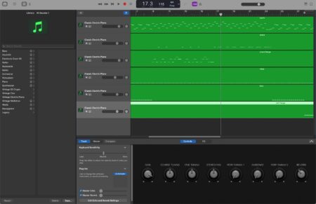
I used Garage Band to import the MIDI track and then assigned a sound sampler to each voice. I loaded the appropriate sample into each one. For some reason I had to transpose a few of the samples to get it sounding just right.
Here is the final track:
If you compare it to the in game music capture, it sounds perfect. Kind of a silly diversion, but nostalgia can be intoxicating! What games from your childhood had memorable music?
Oh man. This music is going to be in my head all day…