It recently became apparent that my son was too big for his toddler bed. As we searched for a twin bed at popular stores for children, I found that beds are grossly over priced. The bed my wife liked was over $600, not including the mattress!
We decided that I could make a better quality bed for much less than that, so I did!
Planning
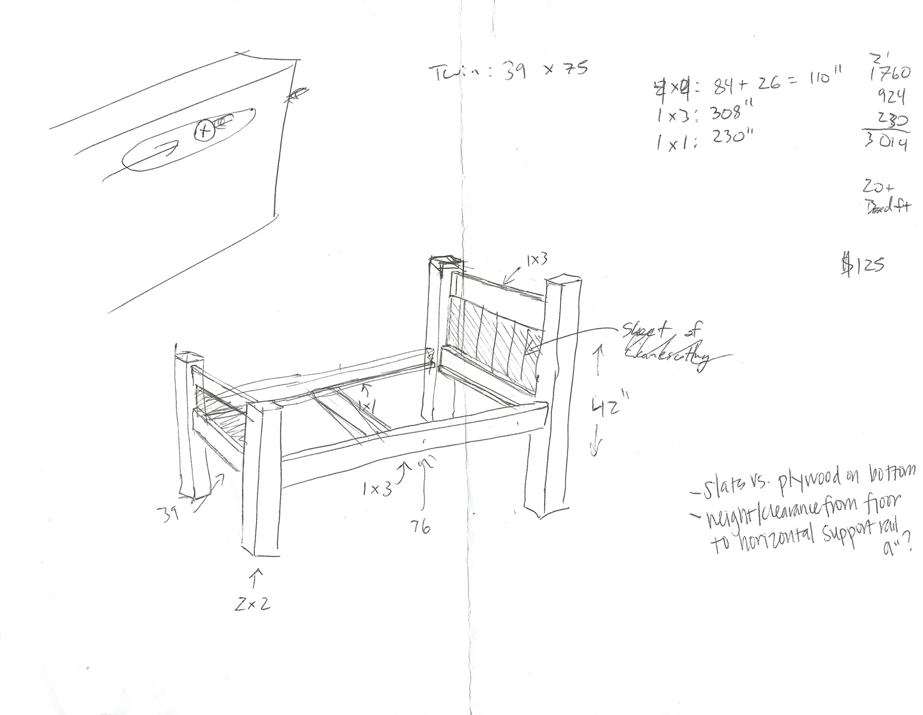
I started out by drawing some hand sketches with rough measurements. I went through the process a few times, each time refining the plan so that it was more complete, and had more accurate dimensions. I also tried to simplify the material selection so there was as little variety in the lumber required as possible.
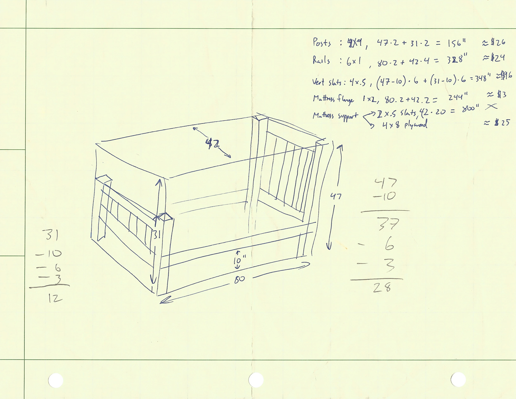
We chose to paint the bed, rather than stain it. This allowed me to choose multiple types of woods which helped cut costs. Here is what was purchased:
| Item | Usage | Quantity | Item Price | Total Price |
| 4×4, 16ft (Redwood) | Bed Posts | 2 | $13.97 | $27.94 |
| 1×6, 24 ft | Lower Bed Rails | 3 | $5.91 | $17.73 |
| 1×4, 8 ft (Spruce) | Head/foot board upper rail | 1 | $1.84 | $1.84 |
| 1×1, 16ft (Poplar) | Mattress Flange | 2 | $3.50 | $7.00 |
| 4×8 3/4″ Plywood | Mattress support | 1 | $38.27 | $38.27 |
| 4×8 1/8″ Plywood | Head/foot board material | 1 | $7.50 | $7.50 |
| 1″ Slats (molding) | Head/foot board decoration | 40 Feet | $.36 | $14.45 |
| Zinsser Primer/Sealer | Prime | 1 Gallon | $19.98 | $19.98 |
| Blue Semi Gloss Paint | Paint | 1 Gallon | $26.97 | $26.97 |
| Total Cost: | $161.68 |
Total cost after tax: $175.90
Bed Posts
 The bedposts are made from 4x4s meant for framing, which come in 8 foot lengths. The posts for the headboard are 4 feet tall, and the posts for the foot board are about 3 feet tall, so there was plenty of wood to get the posts from the 2 lengths that were purchased.
Obviously, the 4×4’s are way too fat for posts on a child’s bed, so I cut them down to 2.7 x 2.7 using a band saw. Next, I sanded them down to 2.5 x 2.5 by taking off .05 inches on each side using a reciprocating drum sander.
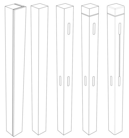
The whole bed was designed to be put together using mortise and tenon joints. The next thing I had to do is put in the mortises. For this, I used a mortise and tenon jig that my dad had. I used the largest setting for all of the mortise and tenons I had to do, which made set up pretty easy since I only had to do it once.
With the mortises all cut, I then needed to add a slot for the 1/8″ sheet of wood that will serve as the head and foot boards. I set up the router with the 1/8″ bit, and a depth of .25 inches, and centered it on the mortises, and made made a groove between the upper and lower mortises on all four posts.
Next, I took the hard edge off the corners by running them each through the router, using a small 1/8 inch quarter round bit.
I designed the bed posts to have a decorative groove near the top. The posts will protrude above the upper rail 2.5 inches, so that the protrusion is a perfect, symmetrical cube of material. I used the golden ratio to decide where to put the groove. The groove was made with the table saw, and is just a single kirf width.
Rails
 The lower rails for the bed frame are made from the 1×6 planks of wood, and the upper rails for the head and foot boards are made from the 1×4 planks of wood.
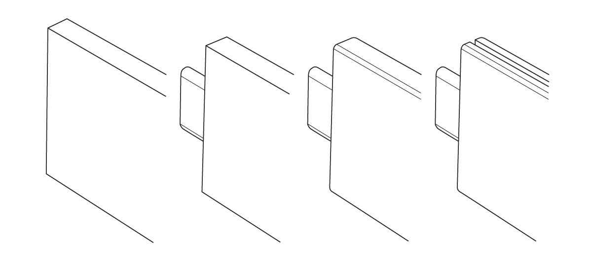
The rails will be supported primarily by the mortise and tenons. I set the tenon jig to cut to a depth of 1 inch, so for the final measurement of the wood, one needs to add 2 inches to account for the tenon.
With the rails all cut to length, and complete with tenons, I routed the corners with the same 1/8″ quarter round that was used on the bed posts.
The shorter of the rails which will be used on the head and foot board require a groove for the head and foot board material. I used the same 1/8″ bit that was used on the posts, and added the groove on one side of all 4 rails at a depth of .25 inches.
Finally, some light sanding, and they are ready for paint.
Head and Foot Boards
The head and foot boards are made up of a 1/8 inch sheet of wood that is inset into the bedposts and rails. This will then be covered with decorative slats.
All I had to do was measure the opening, and add 1/2 an inch to account for the groves in which the wood will be set.
Once cut down to the proper sizes, the head board and foot boards can be assembled. This is done by placing one post down on the table with the mortises face up. The upper and lower rails receive some glue on the tenons which are then inserted to the mortises of the posts, and lightly hammered into place.
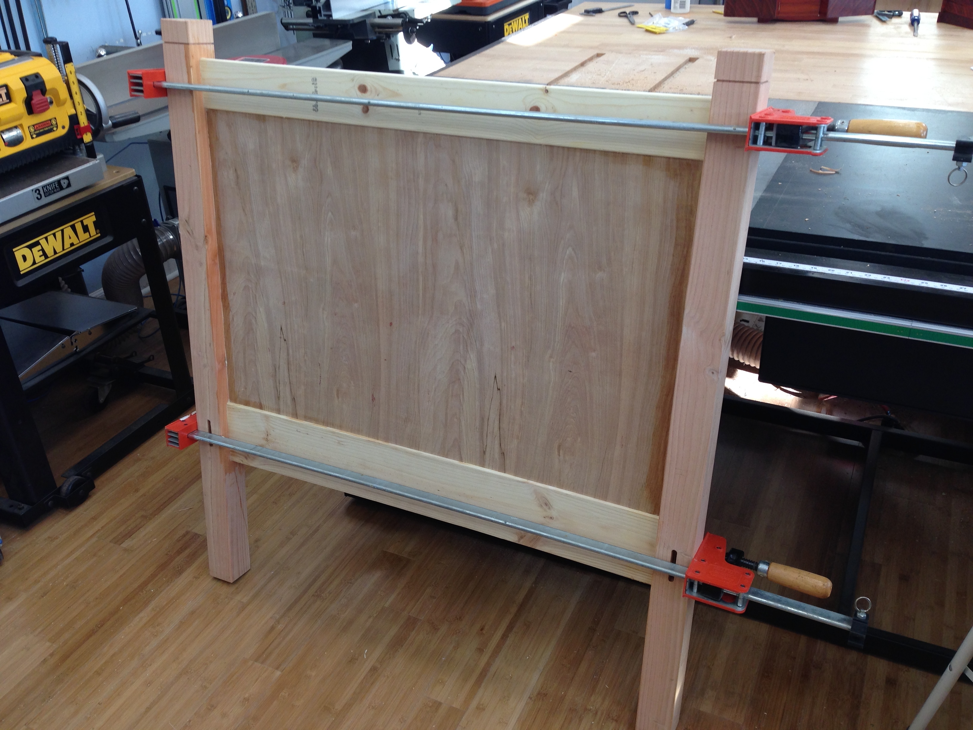 Glue is applied to the exposed grooves. The headboard material is then slid down from the top until it is seated in the groove on the post. Finally, glue is applied to the other end of the rail’s tenons, as well as the end of the headboard sheet, and the other post is tapped into place. The whole thing is clamped for a few hours until the completed headboard is dry.
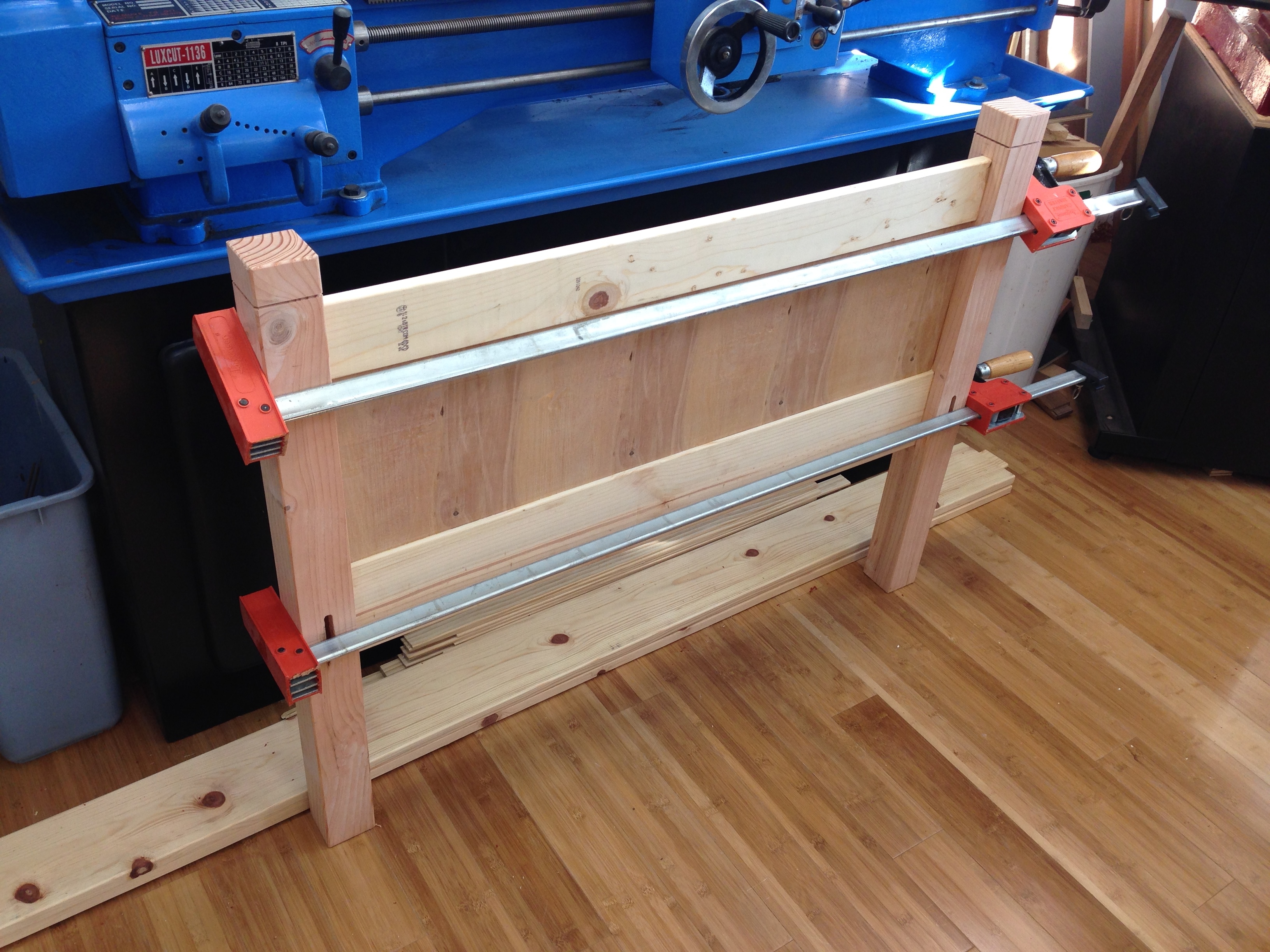 I followed this same procedure for the foot board.
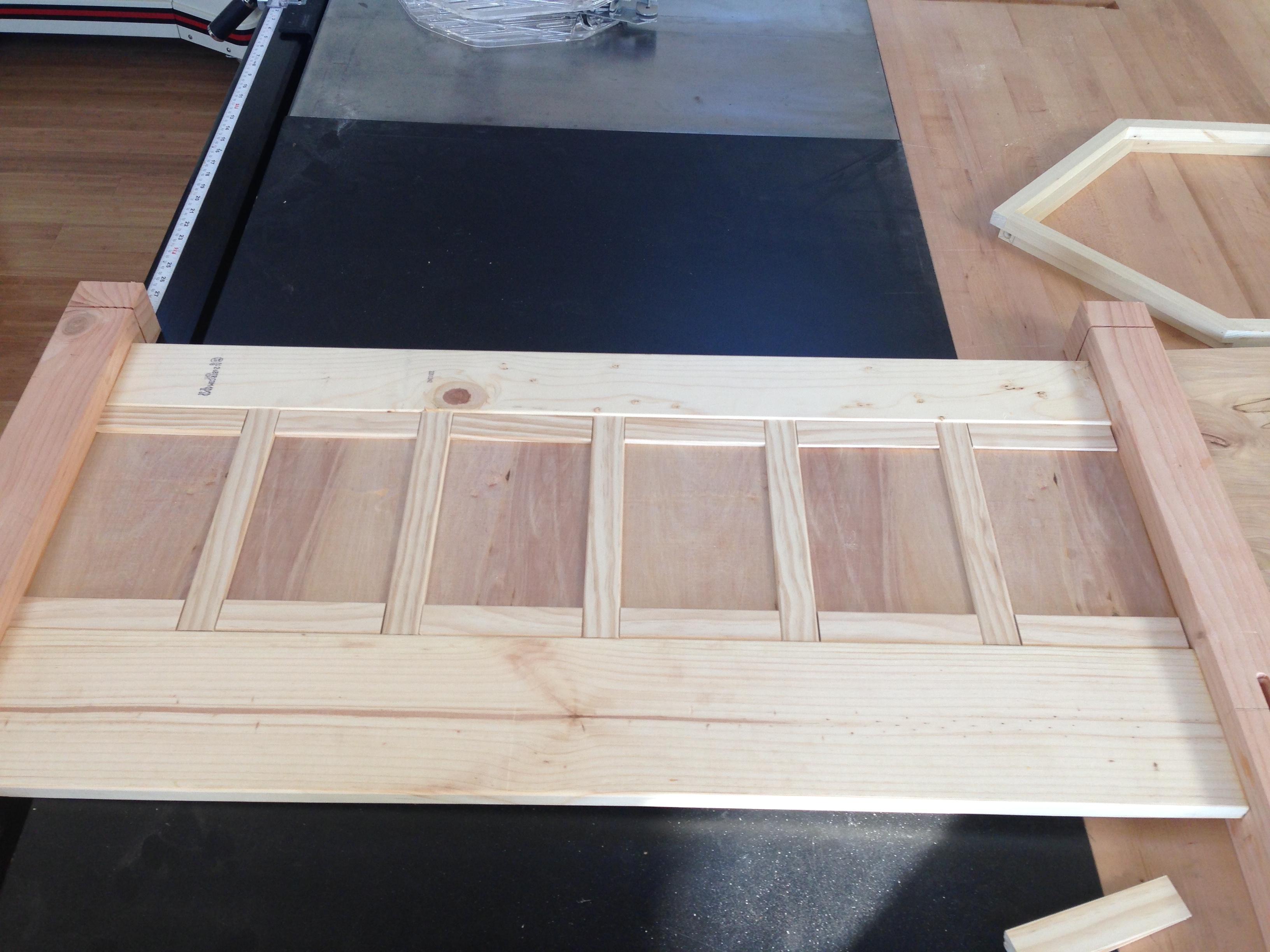 Lastly, slats are added. I took the 1 x 1/4 material and cut it down to the proper length to match the height of the inset area on the headboard. I also used extra material to make spacing jigs to help me distribute the slats evenly across the head and foot boards. They were glued in place. In addition to adding visual interest, the slats add a significant amount of stiffness to the otherwise flimsy 1/4″ material.
Painting
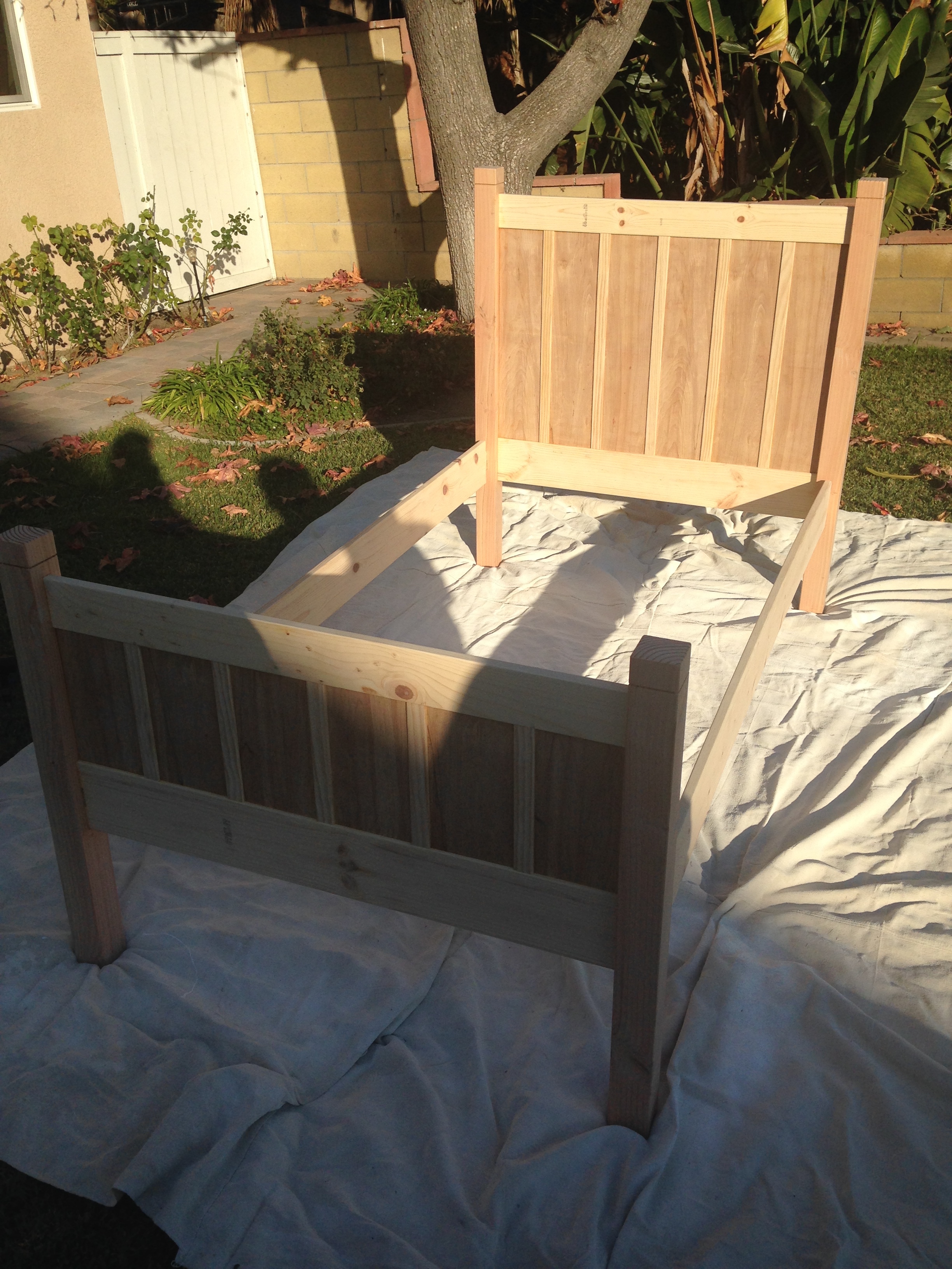 The whole bed was dry-fit together and painted all at once. I masked off a strip on the inner side of the long rails where I planned to put in the flanges that will support the mattress board.
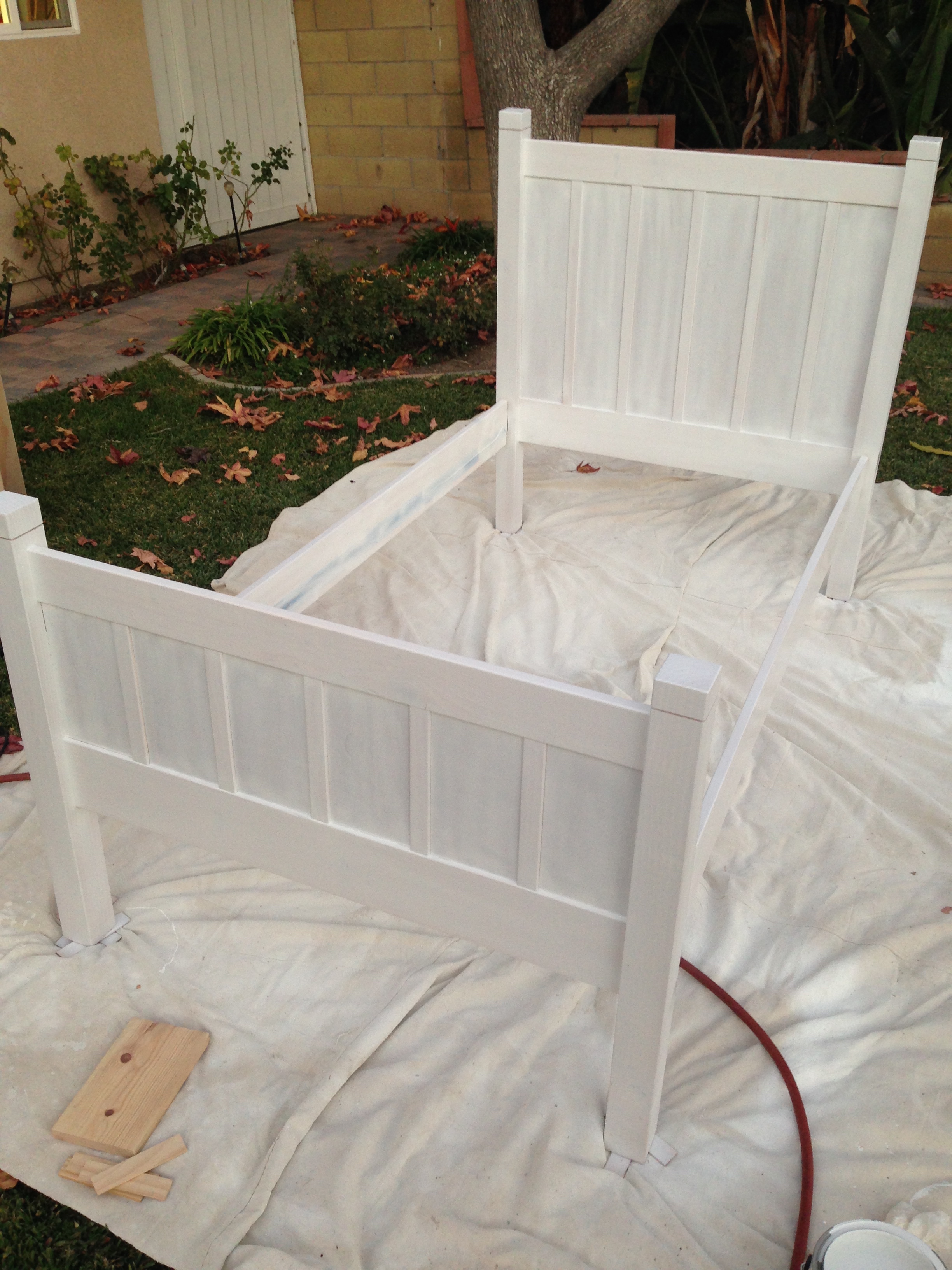 I applied one coat of primer using a gravity fed spraying apparatus for the air compressor. This ended up taking forever due to the small amount of paint that the nozzle delivered. It took about an hour, but was reasonably evenly covered.
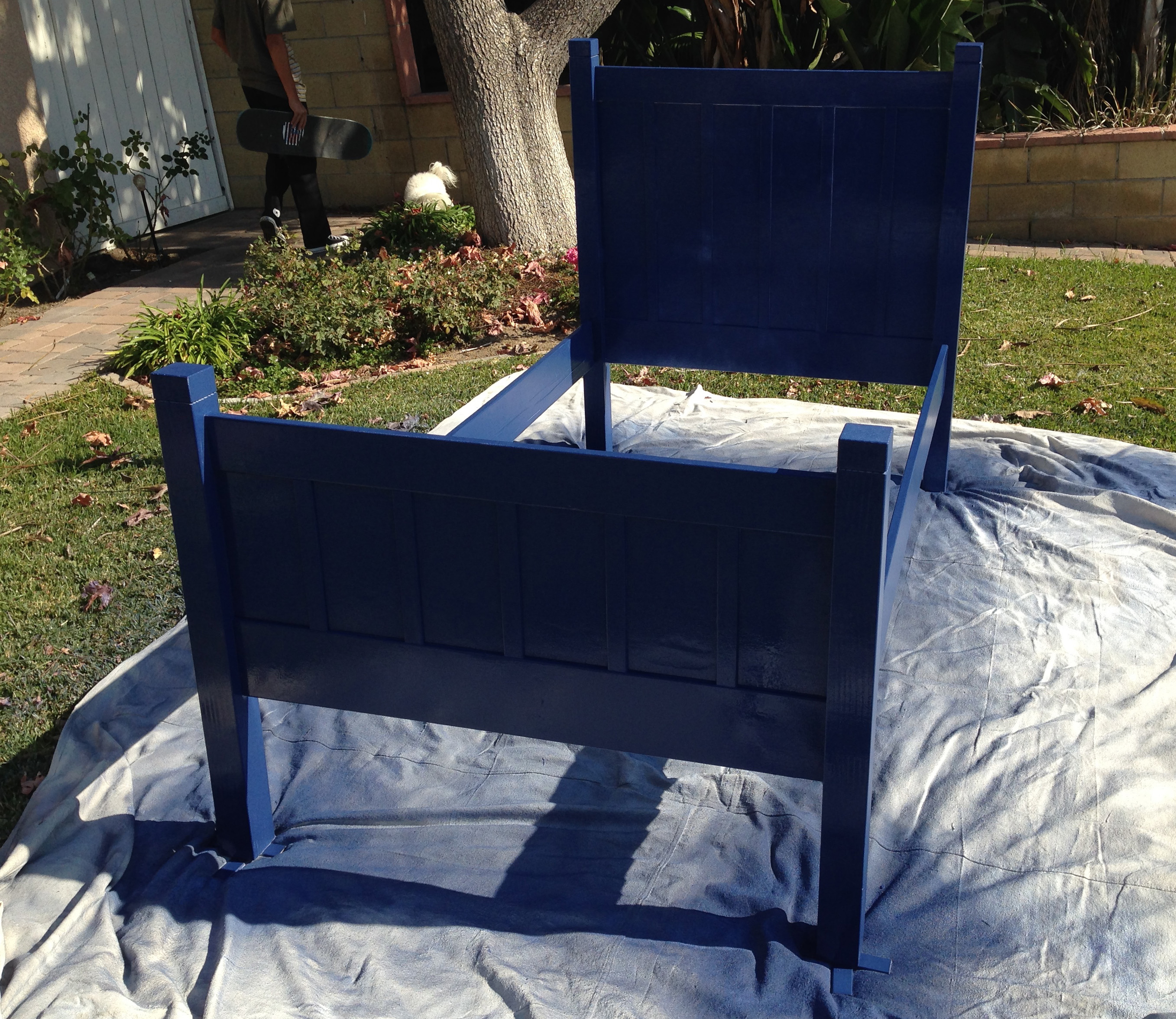 I let the primer dry completely, and then began applying coats of the blue paint using an airless sprayer. The airless sprayer delivered a much thicker coat, and after 3-4 coats of paint, I had used the whole gallon! It looked pretty good though.
Final Touches
Next, I cut the 1×1″ poplar to length, then glued and screwed it to the interior side of the long rails that had been masked off. This will serve as the flange upon which the mattress board will sit, and carry all the weight.
The very last detail before assembly is to drill the holes in the rails that will hold the headboard and foot board together. I used an angled countersink jig to put 2 shallow-angled holes on either end of both rails that will allow screws to hold it tightly to the posts.
With all the pieces reader to go, the bed frame could be assembled. The rails were lightly hammered into the head board posts, then screwed in place.
The foot board posts are then hammered into place on the rails and screwed in.
The mattress board was then cut to snugly fit between the rails, and then laid on top of the flange with the mattress placed on top.
Just add a pillow and some sheets, and the bed is completely finished!
Results
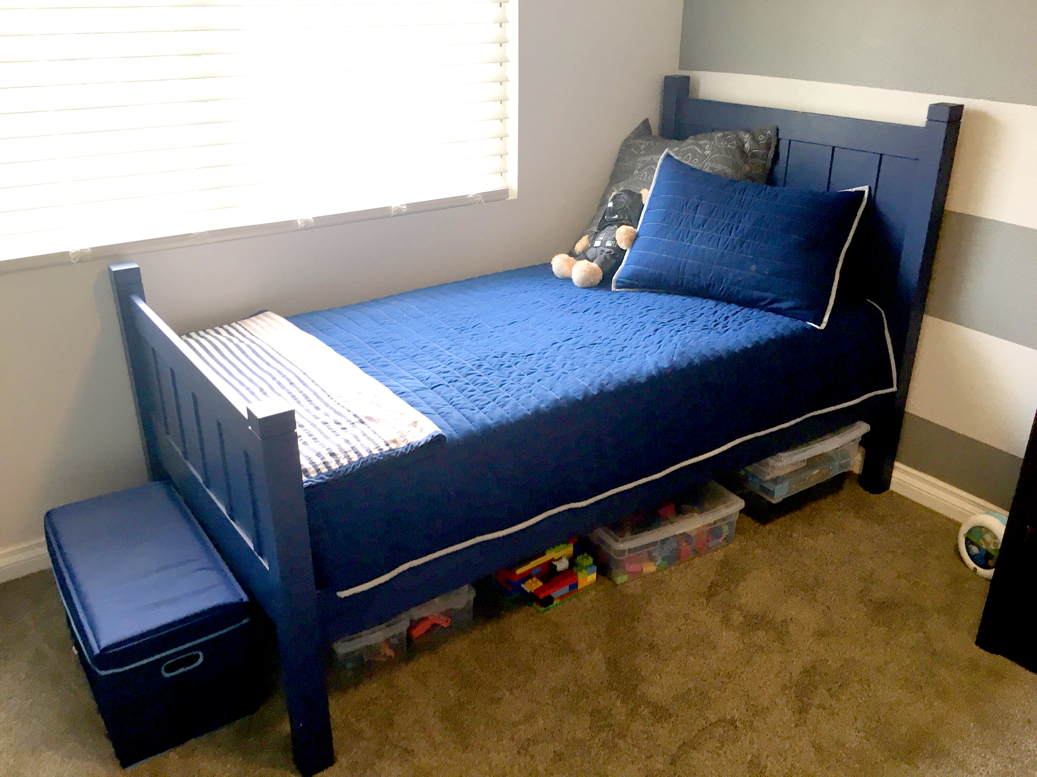
The bed turned out great. It is super-sturdy. No rocking or creaking. The price was also exceptional. The paint has a few minor blemishes due to my inexperience with painting, but looks pretty good overall.
My son loves his new bed, and it’s sturdy enough for all the antics of a toddler.